Core idea
Generate repeatable high-voltage pulses (nanosecond-scale targeted) and couple them into a defined gas path. We prioritize controllability and measurement so results are defensible and reproducible.
A controllable high-voltage pulsed-discharge platform aimed at developing toward nanosecond-scale pulse operation for bench-scale CO₂-related testing. Nanosecond performance is the design goal, while the current prototype focuses on repeatability, measurement readiness, and safe staged bring-up.
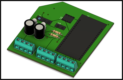
This capstone deliverable is a controllable high-voltage pulsed-discharge platform: pulse-generation electronics, HV conversion, pulse conditioning/protection, a reaction chamber, and basic instrumentation (including mass flow measurement and logging).
Generate repeatable high-voltage pulses (nanosecond-scale targeted) and couple them into a defined gas path. We prioritize controllability and measurement so results are defensible and reproducible.
“Car Filter” is the long-term application framing: a compact module that could be integrated into vehicles to reduce CO₂ emissions. In the capstone timeframe, we are building and validating the prototype platform and test methodology.
Short video update showing the current state of the build and direction.
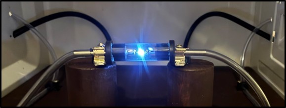
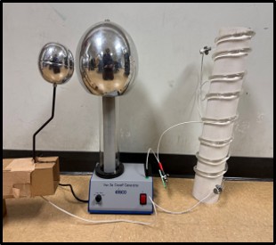
We originally explored a low-frequency, high-voltage spark approach using a Van de Graaff generator. We are now pursuing a nanosecond pulsed-discharge architecture because it supports better controllability, repetition-rate tuning, and measurement-driven iteration.
The first direction used a Van de Graaff generator to create a high-voltage discharge with a more thermal interpretation of CO₂ dissociation. That concept helped shape the early project idea, but it was difficult to control and not well matched to repeatable prototype testing.
Nanosecond pulsed discharge emphasizes fast voltage transitions and repeatable pulse delivery into the chamber. The goal is a controllable electrical drive that supports systematic testing with logged operating conditions.
Establish a baseline chamber and pulser electronics that can be safely brought up and measured.
Improve pulse delivery and discharge stability through electrical and mechanical iteration.
Early testing uses bounded ranges suitable for safe staged bring-up and instrumentation.
Long-term goal: improve efficiency and packaging so the concept could evolve into a compact module compatible with new or existing vehicles. In the near term, we prioritize a safe, repeatable platform and defensible measurements.
Control → pulse generation → HV conversion → pulse conditioning/protection → chamber. Instrumentation includes gas-path hardware and electrical measurements, while accurate flow sensing is still under revision.
The homepage stays visual and high-level. Detailed theory, equations, and deeper hardware notes are on the Progress page.
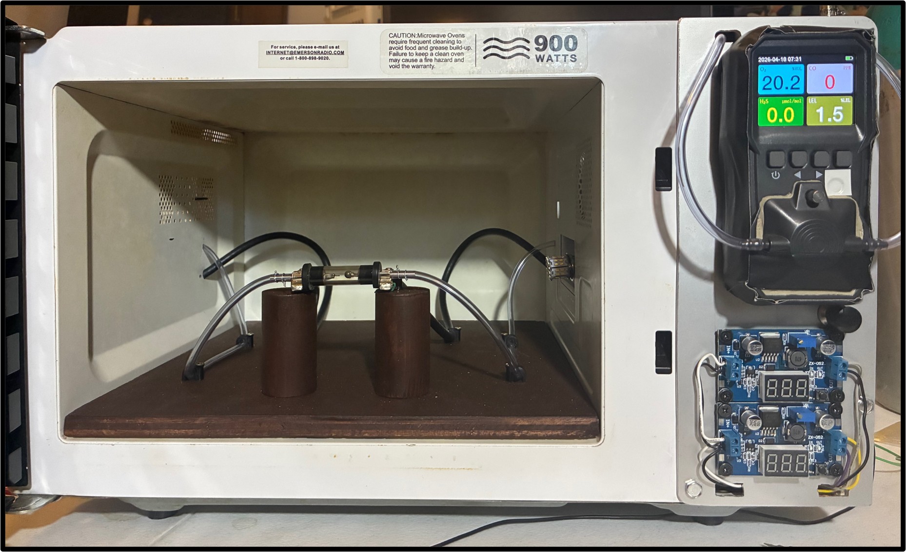
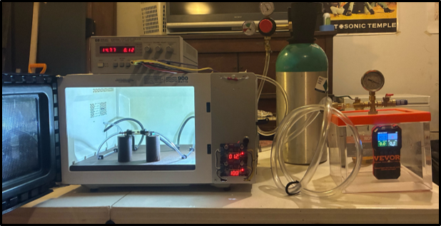
The team has built the chamber, demonstrated spark-gap generation, assembled the full bench prototype, and run CO₂ through the chamber into a handheld analyzer during preliminary testing.
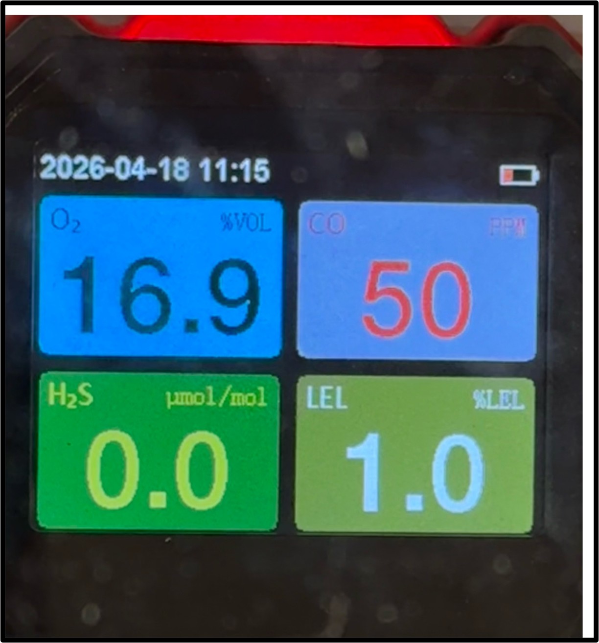
During preliminary testing, the analyzer produced CO readings after the transformer had been running for about 30 seconds to 1 minute, peaking at around 50 ppm. Stronger diagnostics such as gas chromatography or mass spectrometry are still needed to confirm repeatability and rule out confounding factors. The MFC control-and-logging path also still needs revision for reliable flow data.
This project is in the prototype and testing stage. A real bench-scale system now exists, and the next step is improving validation rather than making bigger claims.
The chamber, HV electronics, gas path, and overall bench setup have all been assembled and brought into early testing.
After letting the transformer run for roughly 30 seconds to 1 minute during CO₂ testing, the handheld analyzer showed CO readings that peaked at about 50 ppm. The result is encouraging, but it still requires stronger validation.
Future work will focus on tighter pulse control, better gas diagnostics, and more repeatable testing under controlled conditions.
For detailed build phases, roadblocks, and test plans, see the Progress page.
This is for visitors who want a quick “why it matters” checkpoint before diving into the technical pages.